



High Temperature Resistant Camera Specs You Should Know Before Buying
An inspector points a standard thermal camera at a furnace or kiln. The reading is unreliable—the camera's calibrated temperature range is too low. This scenario shows why the calibrated range is the most important high temperature resistant camera specification. If the camera cannot measure the highest temperature, no other feature can compensate. The required range depends on the measured surface, not the nominal furnace or kiln temperature. Direct views of molten material, refractory, or high-temperature product surfaces may require a 2000°C-class thermal imaging camera. Shells, pipes, insulation, and many surrounding assets often stay within 550°C to 650°C. Buyers should match the range to the actual target, not the process name.
Key Takeaways
Match the camera's temperature range to the actual target, not the process name.
Choose the right spectral range: shorter wavelengths for very hot targets, LWIR for lower temperatures.
Check thermal sensitivity (NETD) to detect small temperature differences.
Ensure the target covers enough pixels (at least 3 × 3) for accurate measurement.
Select the correct field of view and focus for your inspection distance and target size.
Protect the camera with cooling housings and proper IP ratings in extreme heat.
Consider the ZAEX ZASC001 water-cooling housing for high-temperature areas.
Always keep the optical path clear to avoid measurement errors.
High Temperature Resistant Camera Spec: Temperature Range
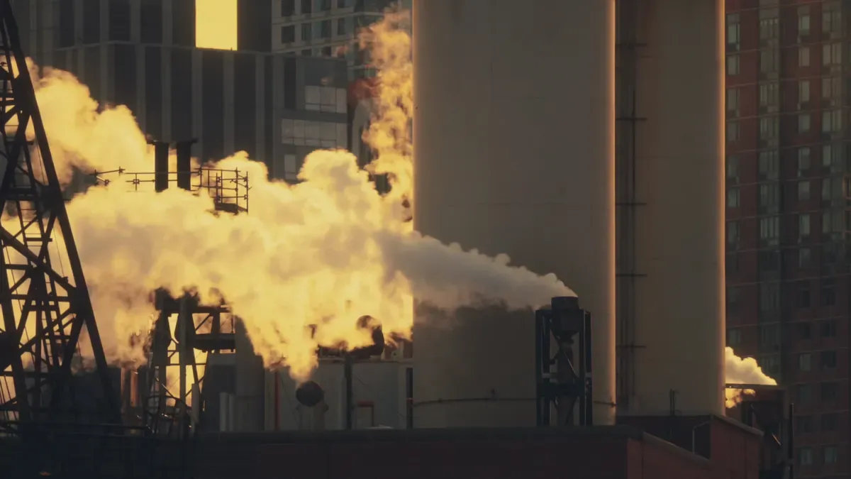
The calibrated temperature range is the first purchase decision for any high temperature resistant camera. Boilers, kilns, furnaces, and similar industrial processes demand careful range matching. A camera rated for 350°C cannot credibly inspect a process that reaches 1,200°C. Out-of-range readings are not approximate. They are unreliable. The camera may saturate, display misleading values, or require a restart after automatic shutter protection activates. Buyers should define the temperature range of their application before comparing any other specifications.
Set Minimum and Maximum Temperature Range
The minimum and maximum limits define what the camera can measure with stated accuracy. Commercial-grade sensors typically operate reliably from -20°C to +70°C ambient. Industrial camera systems from manufacturers like Canon withstand operating temperatures up to 60°C. Enclosure protection standards such as NEMA 4X and IP67/IP68 support ambient temperatures up to 70°C with peak tolerance to 85°C. Research-stage solutions reach 125°C, but commercial availability remains limited. Industrial safety standards from IEC specify performance requirements from 85°C to 200°C. These figures describe ambient operating conditions, not target measurement limits. The measurement range is a separate specification. A camera may measure targets at 1,500°C while its electronics operate safely at 50°C ambient. Buyers must check both ratings independently.
Check Accuracy and Repeatability
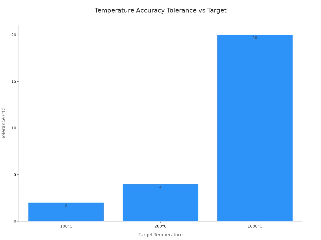
Accuracy determines whether temperature measurements support real decisions. Inspection reports state specific temperatures. Those temperatures may categorize findings as monitor, schedule maintenance, or immediate action. The ±2°C or ±2% radiometric accuracy specification matters because of this decision-making role. Accuracy should reach ±2°C or ±2% to ensure reliable temperature assessment and precise operational decision-making. Modern industrial thermal cameras often specify accuracy of ±1°C or better under defined calibration conditions. The actual value depends on the product model, measurement range, setup, and target surface. A target at 100°C with 2% tolerance gives ±2°C, or 98°C to 102°C. At 200°C, the same tolerance yields ±4°C, or 196°C to 204°C. At 1,000°C, the tolerance reaches ±20°C, or 980°C to 1,020°C. Professional thermal cameras often provide different accuracy specifications per operating range. Buyers should always check the camera datasheet and calibration conditions; measurement science and calibration guidance from national metrology institutes such as NIST underpin traceable temperature measurement.
Avoid Out-of-Range Temperature Measurement
Out-of-range conditions produce errors that mislead operators. A furnace thermography example illustrates this risk. When a peephole door gradually closed, the apparent temperature of the tube dropped even though the actual temperature had not changed. With a maximum temperature of 617°C and a camera accuracy of ±2%, the tolerance is about ±12°C (617 × 2%). Readings below approximately 605°C therefore fall outside the camera's stated accuracy range. From a certain point onward, the readings were out of range. With the door almost closed, the measured temperature was 531°C—86°C lower than with the door fully open. Out-of-range conditions caused by optical obstructions can lead to significant temperature underestimation.
Several factors cause out-of-range errors. Environmental factors include ambient temperature fluctuations affecting detector performance and atmospheric attenuation from water vapor, dust, smoke, and particles weakening infrared radiation. Solar radiation and reflective surfaces cause abnormal surface temperature rises and false high readings. Equipment-related factors include infrared detector sensitivity, resolution, and response speed. Thermal module errors arise from component aging, circuit interference, or incorrect parameter settings. Contaminated or scratched lenses reduce infrared transmittance. Camera-to-target distance and field of view settings cause background interference. Algorithm defects include incorrect emissivity values leading to significant measurement errors and lack of effective noise reduction and background correction.
A practical rule of thumb is not to use the thermal camera on objects whose temperatures exceed the camera's maximum measurable temperature by more than 100°C. When a thermal imager is aimed at an object slightly above its maximum measurement range, the display typically becomes saturated, but the camera usually suffers no damage. If the infrared radiation from a hot source becomes dangerous to the detector, an automatic shutter may close to protect the sensor, and the camera may require a restart. Pointing the imager at extremely hot objects such as the sun, molten steel, or an electric welding arc can damage the infrared sensor. Such situations must be avoided. For measuring high-temperature equipment safely, operators should select a camera with a temperature range required for the application and verify that the target stays within that range during all operating conditions.
Infrared Camera Spectral Range Matters
Spectral range defines the wavelengths of infrared energy an infrared camera detects. Different wavelengths suit different target temperatures. This is why two cameras with identical resolution and accuracy can perform very differently on the same furnace. Shorter wavelengths, such as NIR-SWIR or MWIR, are commonly used for very hot targets. LWIR is better suited for lower-temperature work. Emissivity settings must also match the target surface for consistent readings.
Use NIR-SWIR and MWIR for Very Hot Targets
Very hot targets emit strongly at shorter wavelengths. NIR-SWIR and MWIR sensors capture this energy with less saturation than LWIR sensors. A foundry measuring molten metal or a kiln operator checking refractory brick benefits from this shorter-wavelength response. The signal stays within the detector's useful range, so the thermal imaging cameras produce stable readings instead of clipping at the top of the scale.
LWIR for Lower-Temperature Measurement
LWIR covers the long-wave band and serves most industrial inspection work. The table below shows typical LWIR calibration ranges.
| Temperature Range | Condition / Notes |
|---|---|
| -15°C to 150°C | Standard calibration range; suitable for most research applications |
| 0°C to 850°C | Baseline calibration range |
| -20°C to 650°C | Measurable without requiring an ND filter |
| Up to 650°C | Maximum temperature before an ND filter is needed |
| Up to 2500°C | Extended range achievable with neutral density (ND) filters |
A thermal camera without an ND filter handles targets up to 650°C. Above that point, an ND filter extends the measurable range. Buyers should confirm which calibration range the factory ships with, because the same camera body may support several ranges.
Set Emissivity Correctly for the Target Surface
Emissivity describes how efficiently a surface emits infrared energy. Incorrect emissivity settings directly affect how infrared sensors interpret thermal radiation. A polished aluminum surface with low emissivity may appear cooler than it actually is. A high-emissivity surface may produce a reading closer to reality. Metals generally have low emissivity and are especially prone to errors without proper compensation. Non-metals like wood, plastic, and ceramics tend to yield more accurate readings.
Common error sources include:
Inaccurate emissivity settings, which produce inaccurate temperature readings
Reflections and shadows, which cause the camera to detect a reflected or shaded surface
Distance and angle, which distort readings when the camera sits too far away or at an angle
Environmental factors such as wind, sunlight, and moisture
Corrective steps include using a calibrated thermal camera, setting emissivity based on the material, eliminating reflections and shadows, positioning the camera correctly, and accounting for environmental factors.
Thermal Sensitivity and Temperature Measurement
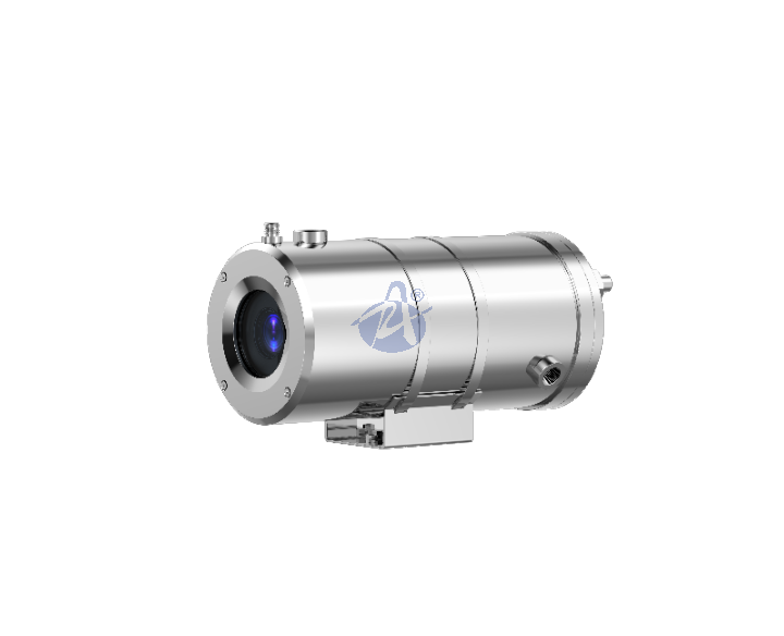
Thermal sensitivity describes the smallest temperature difference a thermal camera sensor can detect. This specification directly affects image quality and the reliability of temperature measurements in industrial settings. A camera with poor sensitivity may miss critical hot spots or produce noisy images that obscure real problems.
What NETD Means in Plain English
NETD stands for noise equivalent temperature difference. Manufacturers measure this value in millikelvins (mK). A lower NETD value means the camera detects smaller temperature differences. For example, a camera with a NETD of 30 mK can distinguish temperature variations of 0.03°C. This capability matters when inspecting electrical connections or mechanical components for early signs of failure.
The table below shows NETD values for several industrial thermal camera sensor models.
| Camera Model | NETD Value | Resolution |
|---|---|---|
| FLIR T865 | <30 mK | 640×480 |
| Fluke Ti480 PRO | ≤30 mK | 640×480 |
| FLIR E96 | <30 mK | 640×480 |
| Fluke Ti300+ | ≤45 mK | 320×240 |
| Fluke TiS55+ | ≤40 mK | 256×192 |
| FLIR E8-XT | <50 mK | 320×240 MSX |
Industry benchmarks and testing standards published by organizations such as ASTM International help classify sensitivity levels. A rating below 25 mK is excellent. Ratings below 40 mK are great, while below 50 mK is good. Below 60 mK is acceptable, and below 80 mK is satisfactory.
When Low NETD Matters Most
Low NETD becomes critical when inspecting equipment with subtle thermal signatures. Electrical panels, motors, and bearings often develop hot spots that differ only slightly from surrounding components. A camera with 35 mK sensitivity handles these inspections well, and ≤40 mK models suit HVAC operations and automotive diagnostics. High-end thermal sensitivity at ≤25 mK suits outdoor observation and advanced diagnostics. Premium levels at ≤20 mK provide extremely fine thermal detail detection. Buyers should match NETD to their inspection requirements rather than defaulting to the lowest available value.
Large Temperature Differences vs. Fine Thermal Details
A furnace tube against a cold background creates a large temperature gap. This scenario does not demand premium NETD performance. The thermal contrast is obvious, and even entry-level cameras capture the difference. The challenge shifts to other specifications like range and spectral response.
Fine thermal details require different priorities. Detecting a loose connection or a failing bearing demands high thermal sensitivity. Thermal sensitivity relates to detectability, not measurement accuracy. The sensor may detect variations in objects too small to measure accurately. Measurement accuracy depends on spot size, which defines the smallest object that can be accurately measured with a given lens and distance. Objects smaller than the spot size may be visible but cannot be measured reliably. Buyers should understand this distinction before selecting a thermal camera for high-temperature industrial work.
Match Resolution to Target Size and Distance
Infrared resolution determines how much detail a thermal camera captures. A higher resolution produces a sharper image. It also helps the camera measure the exact temperature of a specific pixel. Buyers should treat resolution as a measurement specification, not just an image quality feature.
Industrial thermal cameras commonly offer a range of detector resolutions. The table below shows representative models.
| Thermal Camera Model | Infrared Resolution |
|---|---|
| Fluke TiS55+ | 256 × 192 |
| Fluke TiS60+ | 320 × 240 |
| Fluke TiS75+ | 384 × 288 |
| Fluke Ti480 PRO | 640 × 480 |
| Fluke TiX580 | 640 × 480 (up to 1280 × 960) |
| Fluke RSE300 | 320 × 240 |
| Fluke RSE600 | 640 × 480 |
| Fluke Ti300+ | 320 × 240 |
Higher Resolution Improves Temperature Measurement
Resolution affects temperature measurement accuracy, not just image quality. A 320×240 detector contains 76,800 temperature-measuring pixels. It resolves an area smaller than a tenth of a square inch at 6 feet. A 160×120 detector holds just 19,200 pixels. It cannot image anything smaller than twice that size. More background averages into the readings from the lower-resolution sensor. Those readings are inherently less accurate.
The resolution of the thermal camera sensor also shapes the radiometric data a thermal camera produces. Each pixel carries its own temperature value. A denser pixel array places more measurement points on the target. This density supports precise temperature measurement across the inspected surface.
Make Sure You Have Enough Pixels on Target
Pixel coverage on the target decides whether a reading is trustworthy. Manufacturers of thermal imagers recommend that the measured region of interest should be covered with an array of at least 3 × 3 pixels. For specified accuracy, the measured area should be covered by at least 10 × 10 pixels. Only the central 3 × 3 pixels of that 10 × 10 area should be used for the final temperature result. At least seven pixels from the border of the region of interest should be excluded from the temperature calculation. Measurements with a region of interest of only one or two columns of pixels were inaccurate. At a reference temperature of 755°C, the average camera reading was 661°C.
"A target must cover at least 9 pixels on the FPA to be accurately resolved, or else the resulting temperature measurement will be compromised when the camera averages in extraneous background." — Jon Chynoweth, Vice President of Mikron Infrared
Distance changes pixel size on target. A 320 × 240 detector produces pixels measuring 0.086 × 0.086 inches at 6 feet. At 20 feet, each pixel covers 0.288 × 0.288 inches. At 50 feet, pixel size grows to 0.719 × 0.720 inches. A 160 × 120 detector starts at 0.173 × 0.173 inches at 6 feet and reaches 1.437 × 1.441 inches at 50 feet.
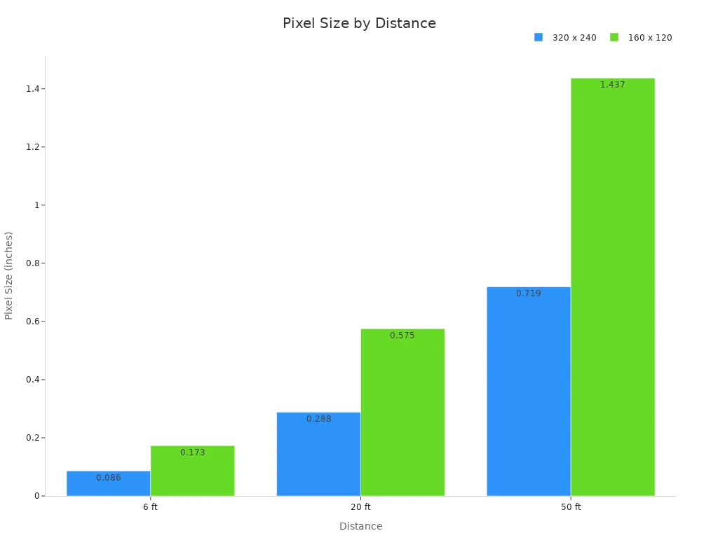
Buyers should calculate how many pixels cover the target across the working distance. This step matters most for small or distant hot surfaces.
Field of View, Focus, and Thermal Imaging Camera Accuracy
Field of view determines how much of the scene a thermal imaging camera captures in a single frame. Buyers should match this angle to the target distance and physical size. A wide angle covers a large area at close range. A narrow angle reaches distant targets with more pixels on the spot. The wrong choice wastes detector resolution or misses the target entirely.
Telephoto Lenses for Distant High-Temperature Targets
Telephoto lenses serve inspections where the camera cannot sit close to the target. Furnace tubes, stack exteriors, and overhead piping often sit far from any safe mounting point. A telephoto thermal camera lens narrows the field of view and projects more pixels onto the target. This optical compression improves the pixel count on a small hot surface across a long working distance.
The trade-off is coverage area. A telephoto view captures a small region, so the operator must aim carefully. Buyers should calculate the horizontal field of view at the working distance before selecting a lens. This step confirms whether the target fits inside the frame with enough margin for movement.
Wide Field of View for Close-Up Inspections
Wide-angle lenses suit close inspections of large surfaces. Refractory walls, tank shells, and electrical rooms benefit from broad coverage in a single image. The operator captures more context per frame and reduces the number of shots needed for a full survey.
Wide angles spread detector pixels across a larger area. Each pixel covers more physical space on the target. Small hot spots may fall below the minimum pixel coverage needed for accurate measurement. Buyers should confirm that the target still fills enough pixels at the chosen distance. A wide lens works best when the target is large or the camera can move closer.
Manual or Autofocus for Accurate Readings
Focus directly affects measurement reliability. A peer-reviewed study on thermal imaging precision treated focus as a prerequisite for valid analysis. Out-of-focus frames were excluded from the dataset because they could not support trustworthy readings. This exclusion reflects a basic principle: blurred infrared energy mixes target and background radiation.
Fluke reports that an out-of-focus thermal image reduces the clarity of captured energy. The resulting reading can be more than 76 degrees cooler than the corresponding in-focus image. Manual focus gives the operator full control over this critical adjustment. Autofocus speeds up the process when the target distance changes often. Either method works, provided the operator confirms sharp focus before recording data. Buyers should review the focus mechanism as part of the thermal imaging camera's specifications, because no other feature compensates for a blurred image.
Protect High Temperature Resistant Camera Hardware
A thermal camera may measure targets at 1,500°C while its own electronics operate safely at 50°C ambient. This distinction matters because the camera body still needs protection from the surrounding heat. A high temperature resistant camera deployed near a furnace or kiln faces ambient conditions that can destroy standard housings. Cooling systems, sealing, and installation planning determine whether the camera survives long-term exposure.
Cooling Housings, Air Purge, and IP Ratings
An air or water cooled housing maintains the camera core within its operating limits. Air purge systems push clean, cool air across the lens and housing interior. This flow prevents dust buildup and keeps the optical path clear. Water-cooling systems circulate coolant through a sealed loop to dissipate heat away from sensitive components. Both approaches extend camera life in high temperature environments.
Ingress protection ratings define how well a housing resists dust and moisture. An IP67 rating means the enclosure withstands temporary immersion. An IP68 rating supports continuous submersion under specified conditions. Corrosion protection matters for coastal refineries and chemical plants. Stainless steel construction and protective coatings resist salt, acids, and industrial chemicals. These features determine reliability in harsh industrial environments.
ZAEX ZASC001 Water-Cooling Housing for High-Temperature Areas
According to the company, the ZAEX ZASC001 water-cooling housing addresses extreme heat zones in refineries, petrochemical plants, and mining sites. It integrates a sealed water circulation loop that dissipates heat away from the camera core. This design helps prevent overheating, image degradation, and premature component failure. The housing maintains explosion-proof integrity while allowing access for installation and service.
The ZASC001 suits industrial applications where ambient temperatures exceed standard camera limits. It resists corrosion, dust, and moisture for both indoor and outdoor installations. Facility managers and safety engineers can deploy this housing in furnace areas, coal gasification units, or steel processing lines. The unit supports round-the-clock monitoring in locations where standard enclosures would fail.
Plan Installation, Wiring, and Maintenance Access
Installation planning affects long-term reliability. Technicians need safe access to the camera for cleaning, calibration, and repairs. Mounting positions should allow adequate clearance for cooling lines and cable routing. Wiring must resist heat, moisture, and mechanical stress. Cable glands and conduit seals protect connections from environmental damage.
Maintenance schedules should include regular inspection of cooling systems. Water lines require checks for leaks, blockages, and coolant quality. Air purge filters need replacement at defined intervals. These steps prevent unexpected failures and extend equipment life. Buyers should confirm that the housing design supports efficient service access before purchase. A well-protected high temperature resistant camera system delivers dependable temperature measurement across its full service life, supported by industrial quality management practices aligned with international standards such as ISO 9001.
Conclusion
Buyers should start with temperature range, then compare spectral range, NETD, resolution, field of view, focus, and environmental protection. No single spec determines high-temperature performance. The combination must match the application. Extreme ambient heat may require an additional cooled enclosure even when the camera itself has a long measurement range. The camera needs protection, not just measurement capability.
Looking for a High Temperature Resistant Camera System?
ZAEX (Changzhou Zuoan Electronics Co., Ltd.) is an ATEX/IECEx certified manufacturer supplying thermal imaging cameras, anti-corrosion stainless steel camera systems, and certified cooling housings including the ZASC001 water-cooling housing for refineries, petrochemical plants, and mining sites. Buyers can request application support, IP ratings, and enclosure certification documents before ordering.
Send an Inquiry to ZAEXView Cooling Housings →FAQ
The required range depends on the measured surface, not the process name. Direct views of molten material or refractory may need a 2000°C-class camera. Shells, pipes, and insulation often stay within 550°C to 650°C. Buyers should match the range to the actual target.
Spectral range defines the infrared wavelengths a camera detects. Very hot targets emit strongly at shorter wavelengths. NIR-SWIR and MWIR sensors handle these targets with less saturation. LWIR suits lower-temperature work. The wrong band produces clipped or unstable readings.
NETD measures the smallest temperature difference a camera can detect. Lower values mean better sensitivity. A rating below 25 mK is excellent. Below 40 mK is great. Buyers should match NETD to their inspection needs rather than defaulting to the lowest value.
Manufacturers recommend at least 3 × 3 pixels on the measured area. For specified accuracy, the target should cover 10 × 10 pixels. Only the central 3 × 3 pixels should provide the final reading. Small or distant targets demand careful pixel calculation.
Yes. An out-of-focus thermal image blends target and background radiation. Fluke reports that readings can be more than 76 degrees cooler than the in-focus image. Operators should confirm sharp focus before recording any data. No other feature compensates for a blurred image.
A camera may measure targets at 1,500°C while its electronics operate safely at 50°C ambient. Extreme ambient heat near furnaces or kilns can destroy standard housings. A water-cooling or air-purge enclosure maintains the camera core within its operating limits.
According to the company, the ZASC001 integrates a sealed water circulation loop into an explosion-proof housing. It dissipates heat away from the camera core in refineries, petrochemical plants, and mining sites. The design resists corrosion, dust, and moisture for indoor and outdoor installations.
No. Glass blocks infrared radiation. Dust, smoke, and water vapor weaken the signal. A furnace thermography example showed an 86°C underestimation when a peephole door gradually closed. Operators should keep the optical path clear for reliable temperature measurement.
References and Image Credits
National Institute of Standards and Technology (NIST) — measurement, accuracy, and calibration science: https://www.nist.gov/
ASTM International — infrared thermography testing standards (e.g., E1934, E1213): https://www.astm.org/
International Organization for Standardization (ISO) — industrial quality and testing standards: https://www.iso.org/
Images — header and illustration images sourced from Pexels and Unsplash (free stock libraries); charts sourced from ZAEX (https://en.zaex.com.cn/)
Notes: NETD and resolution tables list manufacturer-published specifications (FLIR, Fluke); the 617°C furnace example is corrected to a ±2% tolerance of about ±12°C (threshold ≈ 605°C); the 0.25 sq-in / 60 ft measurement claim in the original article was removed because it is inconsistent with the 3 × 3 pixel guidance; ZASC001 product performance is stated according to the company and should be verified with technical documentation before purchase.